clock
 or
or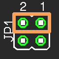
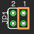
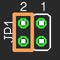
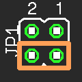
Use here is recommended when the target voltage is 3.3V or less.
| Top Page Index About Link Mail Form |
small and target voltage : 2 3~5V
The kit is sold with Youpit electoronics.
Japanese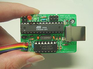
USBasp is In System Programmer for Atmel AVR series. This USBasp is cutomized that it can use at 2 3.0 to 5.0V target voltage. Voltage converter is made referring to AVR-Doper. A special thing to apply the patch is necessary for firmware.
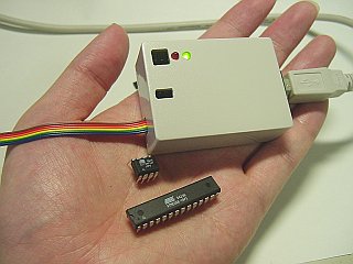
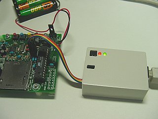
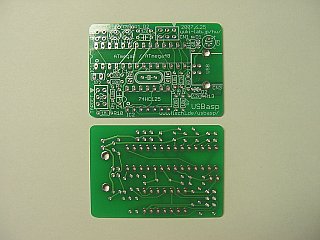
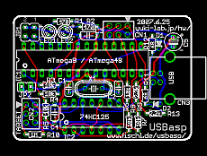
PCB size is 50mm x 35mm. This just enters the TAKACHI SW-55G/B(55mm x 40mm x 20mm). And, Surface Mount Device is not used. However, the beginner might not assemble it easily because it is small.
PCB CAD Eagle source(*.sch *.brd)
Shematic(*.png)
→usbasp.2007-10-23 Version Intel Hex File(ATmega8)
→usbasp.2007-10-23 Version Intel Hex File(ATmega48)
→usbasp.2007-10-23 Version Intel Hex File(ATmega88)
→usbasp.2007-10-23 Version isp.c patch
old version
usbasp.2007-07-23 Version Intel Hex File(ATmega8)
usbasp.2007-07-23 Version Intel Hex File(ATmega48)
usbasp.2007-07-23 Version isp.c patch
usbasp.2006-12-29 Version Intel Hex File(ATmega8)
usbasp.2006-12-29 Version Intel Hex File(ATmega48)
usbasp.2006-12-29 Version isp.c patch
Please use avrdude. If you are Windows user, using avrdude-GUI might be good.
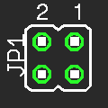
JP1 is for the setting fo ISP clock. Please set it according to Target AVR Clock. Recent AVR is default 1MHz, that it is not possible to write it in the velocity mode. Rewrite the fuse first by a slow setting.
I think It stabilizes when changing to a slow setting when the target voltage is 3.3V or less.
| Jumper setting | ISP clock | target clock | comment |
|---|---|---|---|
 or
or
| 375kHz | 1.5MHz or more | velocity mode(default) |

| about 8kHz | 32kHz or more | using it with slow clock |

| 188kHz | 750kHz or more |
1/2 speed. Special mode that not is original |

| 94kHz | 375kHz or more |
1/4 speed. Special mode that not is original Use here is recommended when the target voltage is 3.3V or less. |
When JP2 is shorted, 5V is supplied to the target board. If a big current is taken, it might influence the personal computer.
| Part Number | Value, Part name | comment |
|---|---|---|
| C1 | 22pF | Ceramic capacitor |
| C2 | 22pF | |
| C30.1uF | ||
| C4 | 0.1uF | |
| C5 | 4.7uF | Chemical capacitor. withstand voltage : 6.3V or more. 10uF can be used. It knocks against on the case if height is not less than 11mm. |
| CN1 | 2 x 3 pin header (for self programming) | Mounting is unnecessary usually. |
| CN2 | 2 x 3 pin header (for target programming) | You may draw out the cable directly though it is indispensable. cut out pin header |
| CN3 | USB-B | USB-B connector |
| D1 | 3.6V Zener diode | 3.3~3.6V |
| D2 | 3.6V Zener diode | |
| IC1 | ATmega8-16PC/16PI | or ATmega48 |
| IC2 | 74HC125 | |
| JP1 | Jumper(2 x 2 pin header) ISP clock setting | cut out pin header |
| JP2 | Jumper(2 x 1 pin header) target power supply | |
| LED1 | Φ3mm(red or orange) | busy indicator |
| LED2 | Φ3mm(green) | power indicator |
| R1 | 470 | 1/6W or small 1/4W |
| R2 | 470 | |
| R3 | 10k | |
| R4 | 10k | |
| R5 | 10k | |
| R6 | 10k | |
| R7 | 10k | |
| R8 | 10k | |
| R9 | 2.2k | |
| R10 | 1M | |
| R11 | 68 | |
| R12 | 68 | |
| R13 | 2.2k | |
| X1 | 12MHz | |
| 28 pin IC sockt(narrow width) | for IC1 | |
| 14 pin IC socket | for IC2 | |
| Case | TAKACHI SW-55G/B | |
| 6 flat cable, 6 pin femail connector, Heat shrinkage tube | cut out pin socket or 6 flat cable |
|
| Jumper short socket | HIROSUGI MJS-1305B etc. |
*The part number is different from original USBasp.